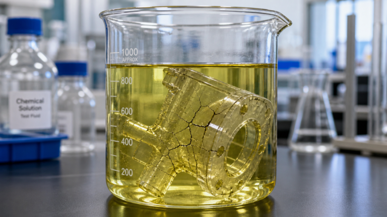
Why Does Ceramic-Filled PEEK Wear Cutting Tools So Quickly?
Your cutting tools are wearing out machining "plastic," and it's costing you time and money. You thought this would be easy, but the material is fighting back.
The hard, abrasive ceramic particles embedded in the PEEK matrix act like fine-grit sandpaper. Each pass of the cutter grinds away at the tool's sharp edge. This abrasive action wears down even tough carbide tools much faster than unfilled polymers ever could.
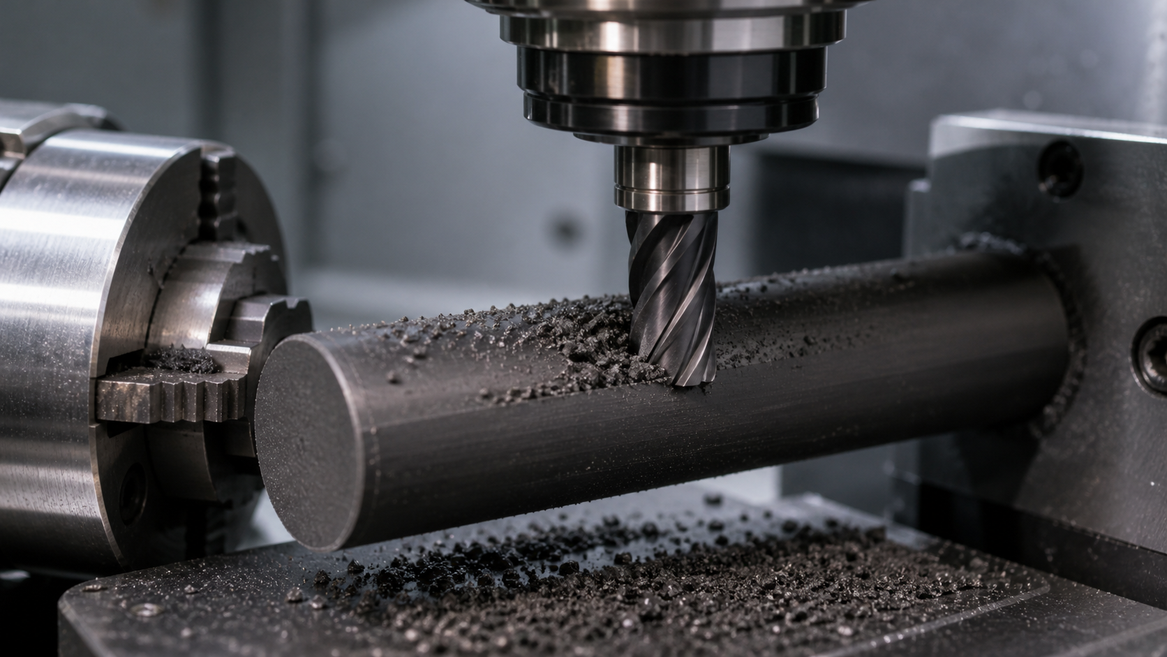
When I first started machining these materials, I was surprised. We were told we were cutting a high-performance polymer, but our tools were failing as if we were cutting metal. It didn't make sense until we stopped thinking of it as just "PEEK" and started focusing on the "ceramic-filled" part. The PEEK itself is relatively easy to cut, but the fillers are a completely different story. They are there to add stiffness, stability, or specific wear properties to the final part. But for the machinist, they are tiny, hard rocks that destroy cutting edges. This realization changed our entire approach. We moved from simply counting parts to actively managing the abrasive process. Understanding why the wear happens is the first step toward controlling it.
Identifying the Ceramic Filler Before Selecting a Cutter?
You know the material is ceramic-filled, but what does that mean? Choosing the wrong cutter for the specific filler can lead to immediate tool failure and scrapped parts.
You must identify the specific ceramic filler, such as silica, alumina, or boron nitride. Harder, larger particles require much tougher cutting tools. We often use carbide tools with a Polycrystalline Diamond (PCD) or a CVD diamond coating to resist the intense abrasion.
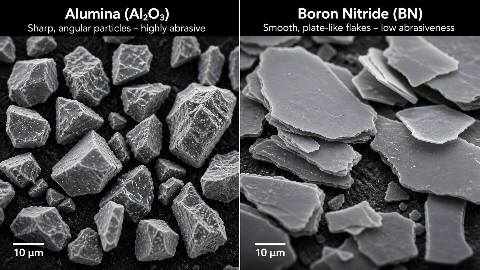
Not all ceramic fillers are created equal. The type, size, and even the shape of the filler particles dictate how aggressively they will attack your cutting tool. Think of it like the difference between rubbing a surface with fine dust versus sharp sand. One polishes, the other rips it apart. We treat every grade of filled PEEK as a unique material until we have machining data for it. We always ask for the material data sheet to see exactly what we're up against.
Filler Hardness and Shape Impact
The hardness of the ceramic is critical. Many common fillers are harder than the tungsten carbide used in standard cutting tools. When a soft tool tries to cut a hard particle, the particle wins every time. It either chips the tool or wears it down through abrasion. This is why we created a simple reference table to guide our initial tool selection.
| Filler Type | Approx. Hardness (Mohs) | Impact on Tooling | Recommended Cutter Type |
|---|---|---|---|
| Boron Nitride | ~2 | Low Abrasiveness | Standard Coated Carbide |
| Silica / Glass | ~6-7 | Moderately Abrasive | Hard-Coating Carbide (TiAlN) |
| Alumina | ~9 | Highly Abrasive | CVD Diamond Coated / PCD |
| Silicon Carbide | ~9.5 | Extremely Abrasive | PCD Tooling Essential |
This table is just a starting point. We always confirm our approach with a test cut. We treat this discussion as anecdotal and would independently confirm any proposed remedy for a specific grade we are machining.
Tracking Abrasive Damage Along the Cutting Edge?
You think your process is stable, but then your parts start going out of tolerance. The tool wear was happening all along, you just couldn't see it until it was too late.
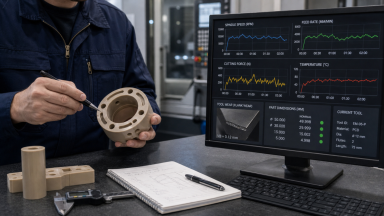
We track abrasive damage by regularly removing the cutting tool to inspect its edge under a microscope. We look for specific wear patterns like edge rounding and flank wear. Documenting these changes helps us predict when the tool will start producing bad parts.
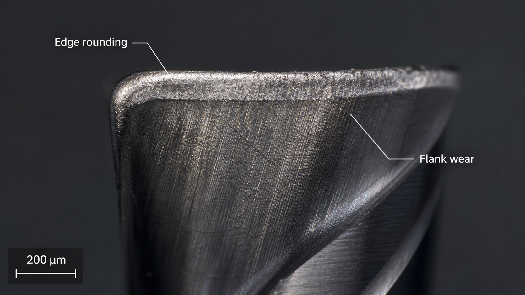
Relying on a simple part count to decide when to change a tool is just guessing. We learned this the hard way after scrapping a whole batch of expensive parts. Now, tool inspection is a non-negotiable part of our process for abrasive polymers. We start with a brand-new, sharp cutting edge as our baseline. Then, after a set number of parts or a specific time interval, we take the tool out of the machine and put it under the scope. We're not just looking to see if it's "dull." We are looking for specific types of damage that tell us a story about how the tool is failing. This detailed feedback allows us to make small adjustments to speeds, feeds, or even the toolpath to extend the tool's life and maintain part quality. It feels like extra work at first, but it saves us enormous headaches and cost in the long run.
Relating Edge Wear to the Length of Cut?
You change your tool every 50 parts, but sometimes it fails at 30 and sometimes it's still good at 70. This inconsistency makes production planning a nightmare.
We relate edge wear directly to the total length of cut, not just the number of parts. A tool machining a long, deep feature wears faster than one making a small hole. By tracking the actual distance the tool travels, we create a much more accurate model for predicting tool life.
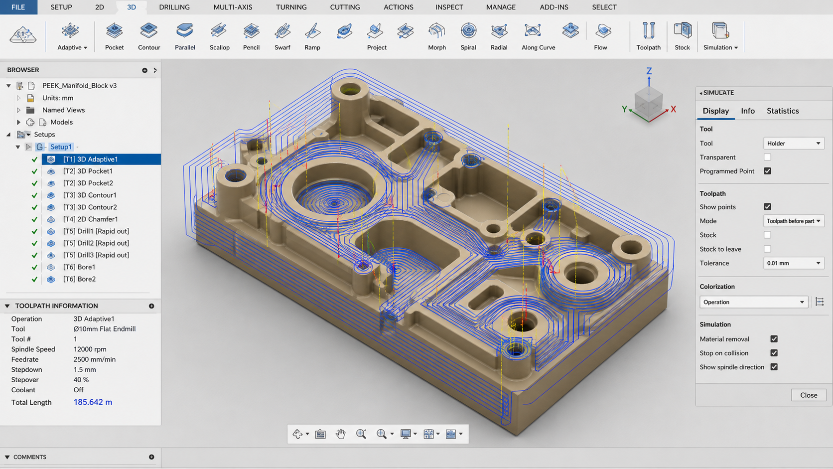
The idea that all parts are equal in terms of tool wear is a major flaw in many production plans. We stopped thinking in "parts per tool" and started thinking in "meters per tool." Most CAM software can calculate the total distance a tool travels to create a feature or a full part. This number is our key metric. For example, machining a simple ring might involve 10 meters of cutting. A complex manifold block from the same material might involve 200 meters. A tool will obviously not last for the same number of parts in these two scenarios. By logging the accumulated cutting distance and comparing it to the wear we see under the microscope, we can build a very reliable wear curve for a specific tool and material combination. This data-driven approach removes the guesswork. It allows us to predict, with high confidence, how long a tool will last in any given job.
Scheduling Changes Before Critical Features Drift?
An unexpected tool failure stops the whole production line. Now you're behind schedule, dealing with scrap parts, and trying to figure out what went wrong under pressure.
We use our wear data to schedule tool changes proactively. Once we know that a tool's edge degrades after a certain cutting distance, we plan a replacement before it reaches that failure point. This simple step prevents critical dimensions from drifting out of tolerance.
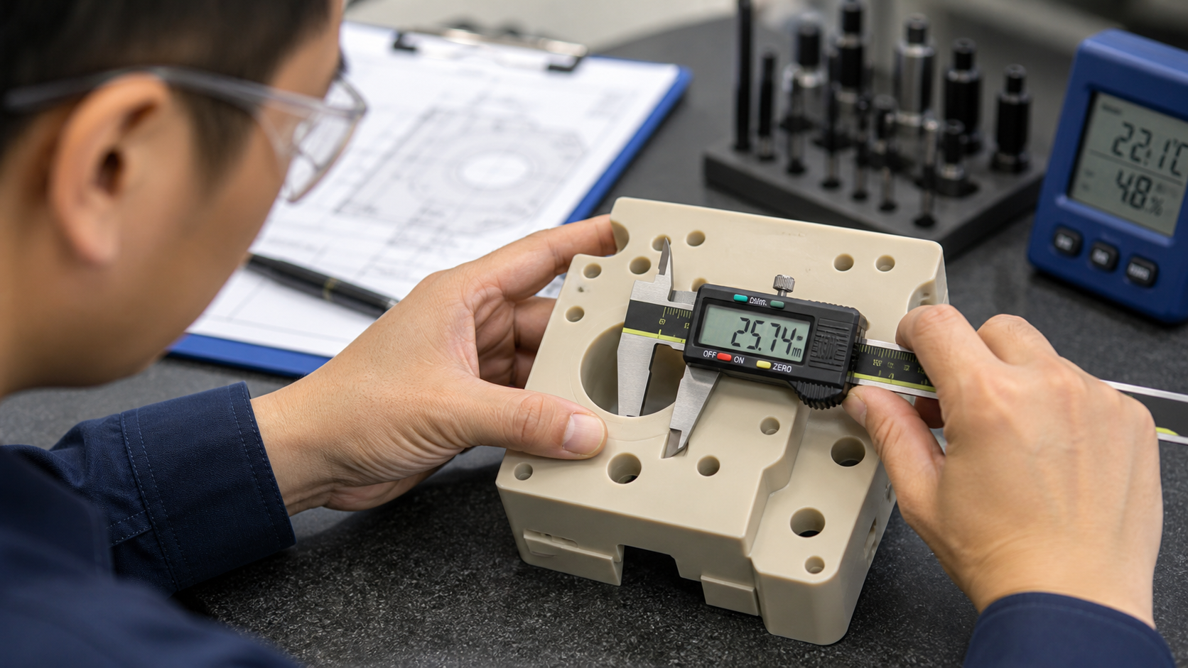
This is where all the previous steps come together to create a robust and predictable process. We combine our knowledge of the filler material, our microscopic wear analysis, and our length-of-cut data to create a simple rule: "For this material, with this tool, we will change the tool every 150 meters of cutting." This change is scheduled into the production plan just like any other maintenance task. It is not an emergency stop; it is a planned event. To verify our model, we also increase the frequency of our dimensional checks. On a long run, we might measure a critical feature on every 10th part. If we see a dimension slowly starting to "drift" toward a tolerance limit, we know our tool is wearing as expected. This allows us to make the change before any parts are actually out of spec. This proactive approach turns tool wear from a chaotic problem into a managed, predictable cost.
Conclusion
We treat abrasive tool wear in ceramic-filled PEEK as a manageable process variable. By identifying the filler, tracking edge wear, and scheduling changes, we make tool life an evidence-based decision.