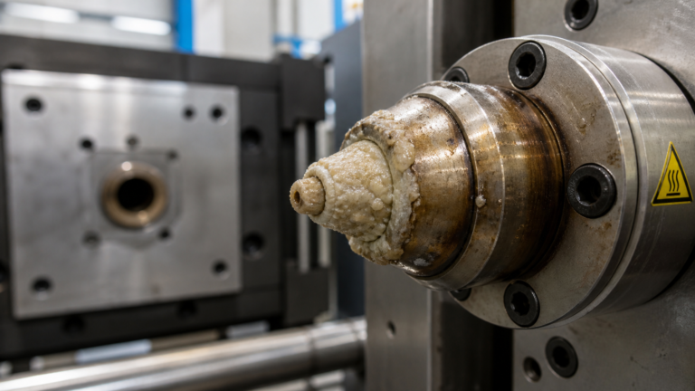
Can More Spindle Speed Make a PEEK Hole Worse?
Drilling PEEK seems easy, but pushing for a better finish by increasing speed can lead to melted, messy holes. Understanding the balance between speed and heat is the key.
Yes, more spindle speed can absolutely make a PEEK hole worse. Excessive speed generates heat much faster than the material or tool can remove it. This causes the polymer to melt, smear around the hole, and create a poor, dimensionally inaccurate finish with high internal stress.
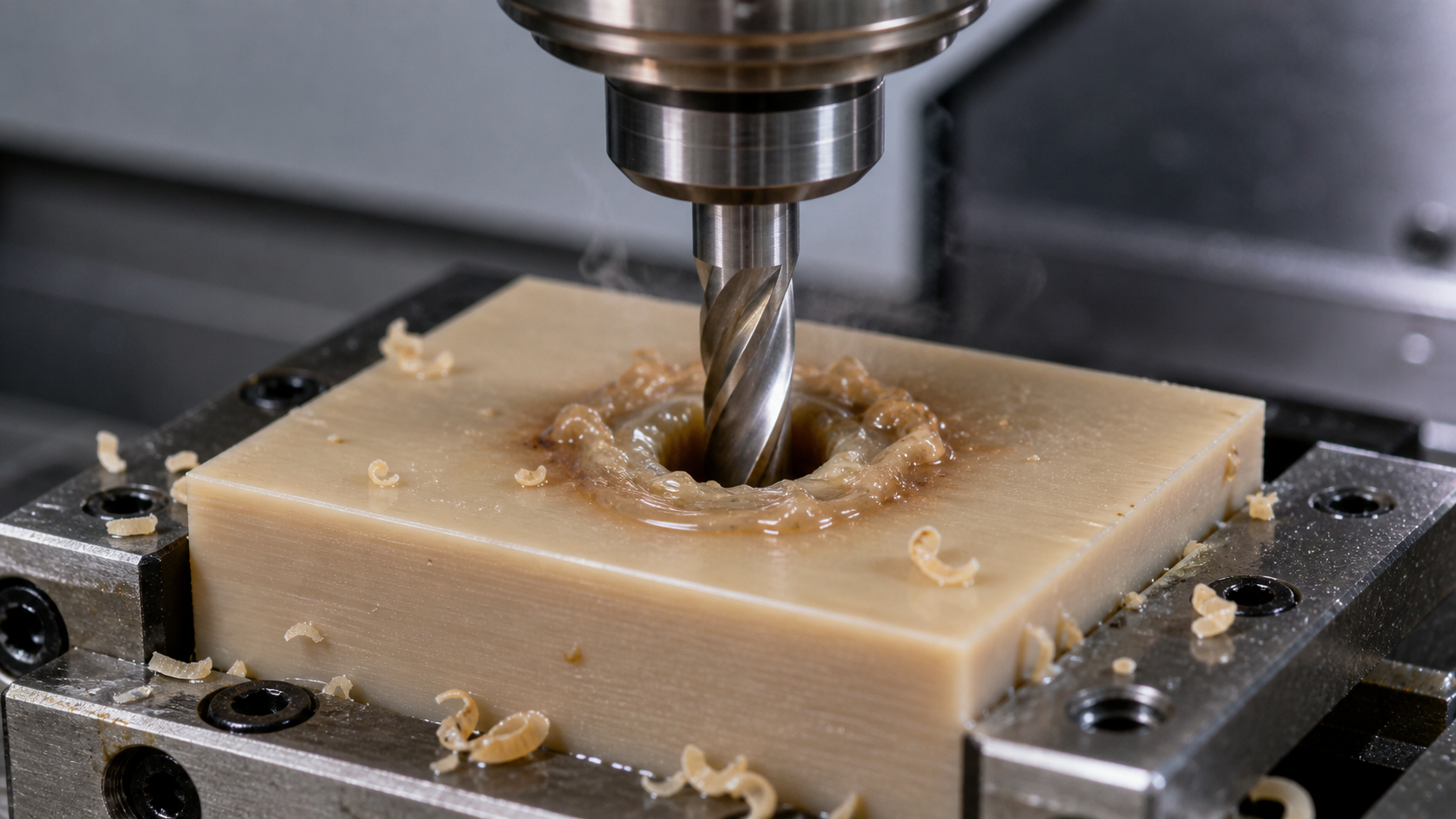
I've seen it happen many times. A machinist gets a new job working with PEEK and thinks of it like aluminum. They crank up the RPM, expecting a mirror finish, and instead they get a gummy mess. The problem is that plastics, especially high-performance ones like PEEK, don't conduct heat well. All the energy from the cutting action gets concentrated right at the tool tip. If you don't manage that energy, you stop cutting and start melting. This is why a successful approach to drilling PEEK isn't just about speed; it's about a complete strategy. We need to look at the evidence the material gives us, starting with the chips it produces.
Comparing Chip Formation as Speed Increases?
You need to know if your cutting speed is right, but guessing can lead to scrapped parts and wasted time. The solution is simple: look at the chips. They tell the whole story.
As speed increases, ideal PEEK chips change from long, continuous ribbons to smaller, well-formed segments. If the chips become discolored, gummy, or start welding together, it is a clear sign of excessive heat. This is your first warning that you are running too fast for the current conditions.
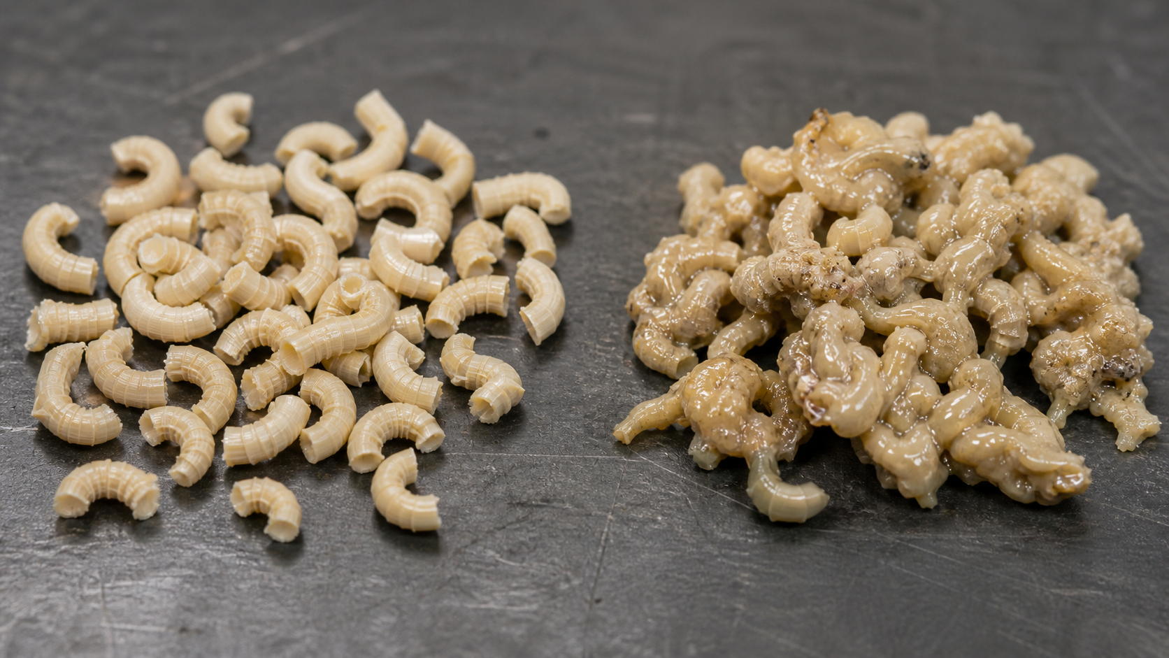
When we teach new machinists about plastics, the first thing we show them is how to "read" the chips. It's the most immediate feedback you can get from the cutting process. For a material like PEEK, what we're looking for is a clean shearing action. At the right speed and feed, the tool cuts a chip that curls and breaks off cleanly. At slower speeds, you might get a long, stringy chip, which isn't necessarily bad but can cause problems with wrapping around the tool. As you increase speed, you should see those strings break into smaller, more manageable pieces. This is often the sweet spot. But if you push the speed too far, the heat changes everything. The chips stop being cut and start being torn and melted. They will look shiny and feel sticky, and you might see them clumping together instead of flowing out of the hole.
Chip Condition vs. Spindle Speed
We often create a small test piece to dial in our parameters. Here is a simple breakdown of what we look for.
| Spindle Speed | Chip Appearance | What It Means |
|---|---|---|
| Too Low | Long, continuous, stringy ribbons | Inefficient cutting. Risk of chips wrapping the tool and damaging the hole surface. |
| Optimal | Short, segmented, uniform “C” or “6” shapes | Clean shearing action. Good balance of cutting efficiency and heat control. |
| Too High | Gummy, melted, discolored, or welded clumps | Excessive heat generation. The material is melting, not cutting, leading to a poor finish. |
This simple observation is an evidence-based approach. We aren't relying on a generic datasheet; we are watching how this specific grade of PEEK responds to our tool on our machine today.
Checking for Local Heating Around the Hole?
The hole looks bad, but you aren't sure if it's the tool or the speed. Heat damage can ruin a part's mechanical integrity, so you need to know what to look for.
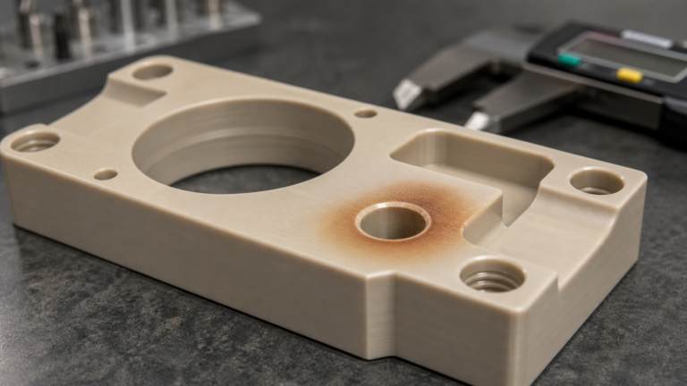
Look for a raised burr or a glossy, melted-looking ring around the hole's entrance and exit. The inside surface of the hole might feel sticky or show smears instead of clean tool marks. These are all clear indicators of local heating, where the PEEK has exceeded its glass transition temperature.
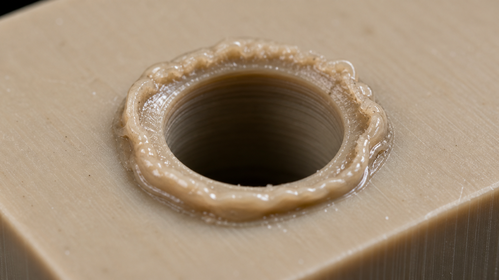
PEEK is a poor thermal conductor. This is a great property for many applications, but a major challenge in machining. It means that the heat generated by friction between the tool and the material doesn't spread out and dissipate. It stays concentrated right where you are cutting. If that heat builds up faster than you can remove it (either in the chip or with coolant), the local temperature of the PEEK will skyrocket. PEEK has a glass transition temperature (Tg) of around 143°C (289°F). Above this temperature, the material softens dramatically. You might not be at the full melting point of 343°C (649°F), but you are high enough to cause smearing, burrs, and high residual stress in the material around the hole. In one extreme case, I saw a hole that was drilled so hot that after it cooled, you could see stress cracks forming around it because the material had expanded and then contracted so violently.
Separating Better Cutting From Heat-Damaged Finish?
Sometimes a higher speed can feel like a smoother cut, yet the final surface finish is still poor. You have to learn to tell the difference between a clean shear and a melted smear.
A true "better cut" from higher speed means the tool shears the material cleanly before significant heat can build up. A heat-damaged finish happens when friction generates enough heat to melt the surface, which then re-solidifies into a smooth but dimensionally inaccurate and stressed surface.
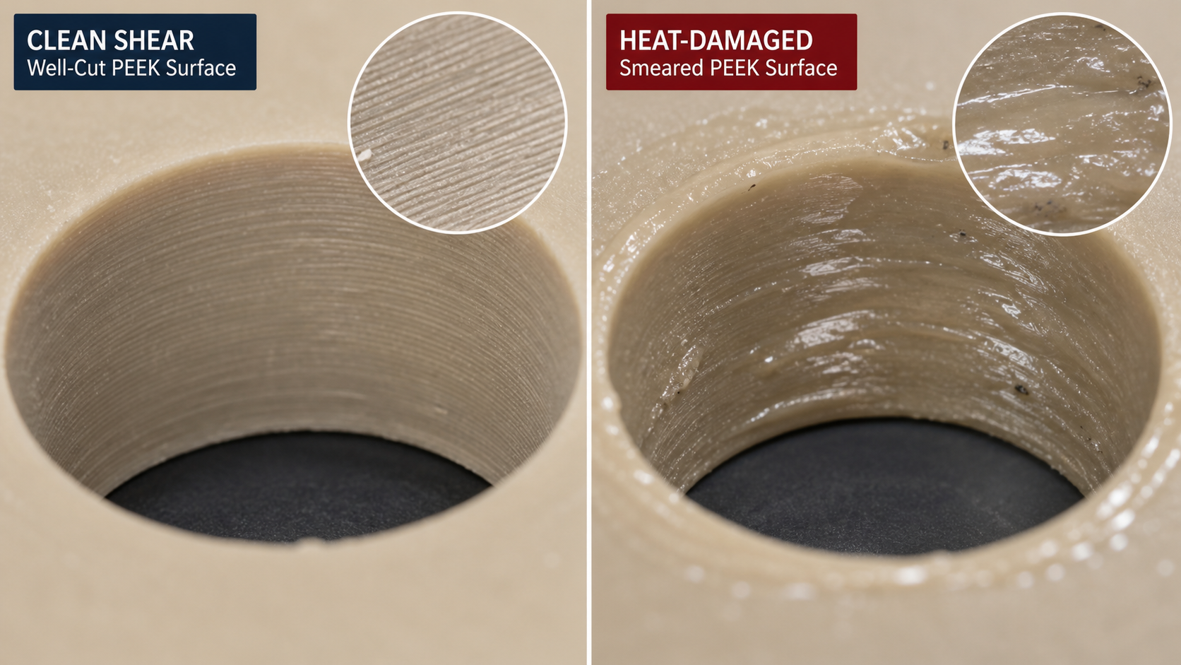
This is a subtle but critical point. A machinist might see a shiny surface inside the hole and think they've achieved a great finish. But under magnification, the story is different. A cleanly cut surface will show fine, regular tool marks, indicating that material was removed by shearing. A heat-damaged surface will look smooth and glossy because it's not a cut surface at all; it's a re-solidified melted surface. Think about cutting a block of cold butter with a sharp knife versus spreading soft, warm butter. The first gives you a clean, defined surface. The second gives you a smooth, smeared surface. That smeared PEEK surface is dimensionally unpredictable and has high internal stress locked into it, which can cause the part to warp later or fail under load. The key is to use very sharp tools with positive rake angles designed for plastics. A sharp tool minimizes friction and promotes a clean shearing action, which is the foundation of good machining in any polymer.
Selecting Speed Alongside Feed and Chip Evacuation?
You have tried adjusting the speed alone, but you are still getting bad results and maybe even breaking small drill bits. The solution is to treat speed as just one part of a three-part system.
Spindle speed should never be selected in isolation. It must be balanced with the feed rate to maintain a proper chip load. More importantly, both speed and feed must allow for effective chip evacuation to prevent chips from packing up, melting, and ruining both the tool and the part.
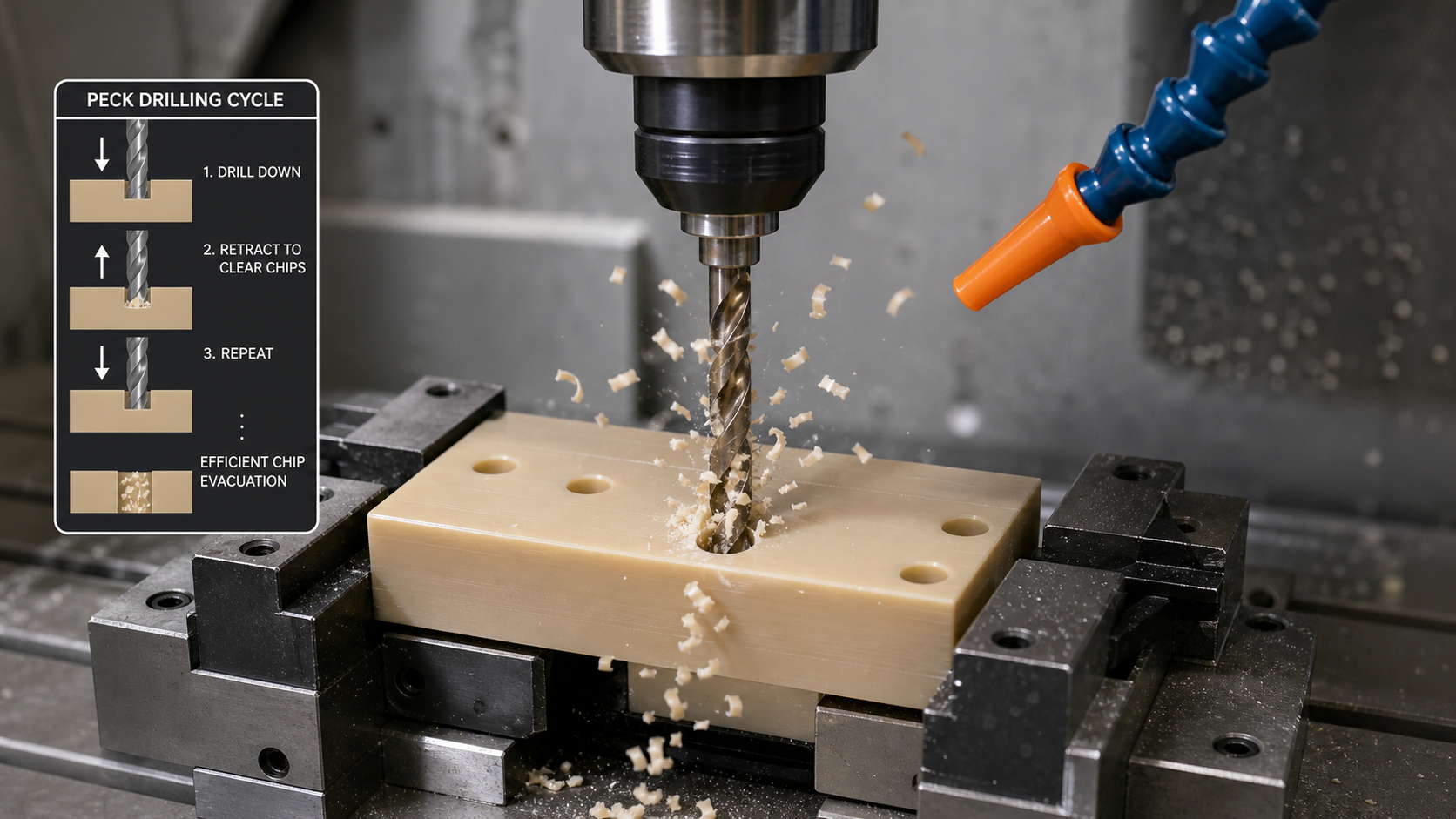
This is where everything comes together. Speed (RPM) and feed (mm/rev or inch/rev) work together to determine your "chip load," which is the thickness of the material each cutting edge of the drill removes. If you have a high spindle speed but a very low feed rate, the tool is essentially just rubbing against the material instead of cutting it. This rubbing action generates a massive amount of friction and heat with very little material removal. Conversely, too high of a feed rate can overwhelm the tool and break it. Finding the right balance is key. But even the perfect speed and feed are useless if you can't get the chips out of the hole. For small or deep holes in PEEK, this is the number one challenge. The chips pack inside the flutes, the friction skyrockets, and the tool and workpiece melt together. We always use a peck drilling cycle for holes deeper than two or three times the drill diameter. This retracts the drill regularly to clear the chips and allows heat to dissipate.
Conclusion
Do not just increase speed for PEEK. Watch your chips, check for heat damage, and always balance your speed with an appropriate feed rate and a solid strategy for chip evacuation.