Should a PEEK Mold Use Oil Heating or Cartridge Heaters?
Molding high-temperature polymers like PEEK can be tricky. You might struggle with part quality, even when the machine settings seem right. The real problem is often hidden inside the steel.
The best choice depends on your tool's complexity and the required temperature uniformity. We use thermal mapping to analyze heat distribution. This evidence-based approach helps us decide if oil circulation's overall control or cartridge heaters' targeted power is the better fit for the specific PEEK component.
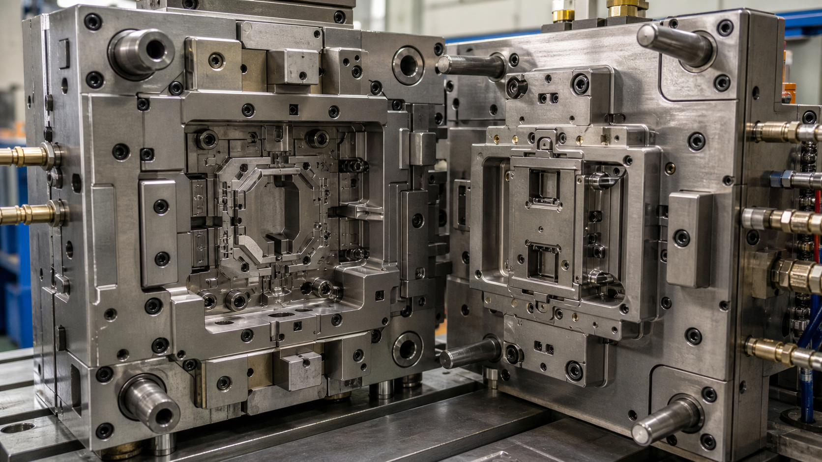
When we work with materials like PEEK, we have to think differently. The rules that apply to polypropylene or ABS don't work here because PEEK needs a very hot mold, often around 170-200°C, to achieve proper crystallinity and dimensional stability. Getting the mold steel to that temperature is one thing, but keeping it there uniformly is the real challenge. Many processors default to the heating method they know best, but that can be a mistake. A simple part might do well with circulating oil, but a complex geometry with thin walls and thick bosses could have cold spots that ruin the final component. We don't guess. We look at the evidence. This means we prioritize understanding the actual hot-tool temperature across the entire cavity surface over sticking with familiar methods from lower-temperature resin processing. Let's explore how we make this an evidence-based decision.
Following Heat Paths Through a Complex Tool?
Your PEEK parts have inconsistent properties or warp after cooling. You've checked the resin and the machine, but the issue persists, likely originating from uneven temperatures inside the mold itself.
We trace the flow of heat through the mold steel from the source to the cavity surface. This involves analyzing the tool's geometry, material, and insulation to understand how different sections heat up and cool down, which directly impacts the PEEK part's final structure and stability.
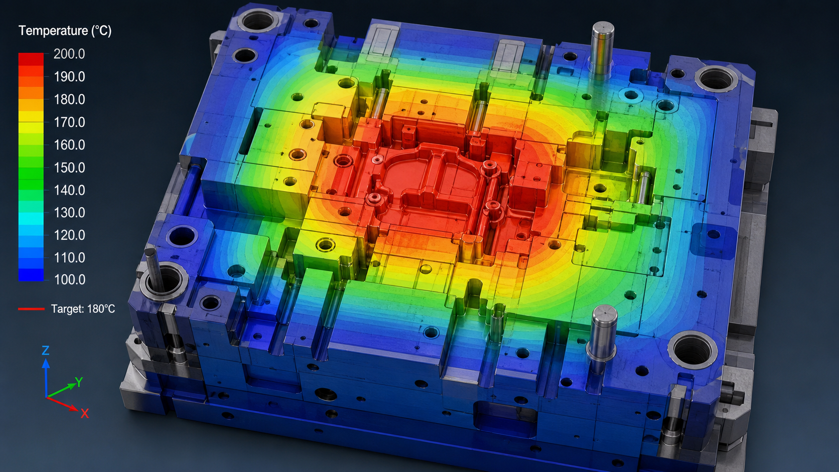
Heat doesn't just appear where you want it. It has to travel through the steel of the mold. Think of it like water flowing through pipes. The "pipes" in this case are the steel blocks of your tool. Steel is a decent conductor, but it's not perfect. Heat will always take the path of least resistance, and it can get "stuck" or "slowed down" in certain areas. For example, a thin steel section between the heating element and the cavity wall will heat up much faster than a thick, massive block of steel. If your part has complex features like deep ribs or isolated cores, these areas can be very difficult to heat evenly. We have to consider how far the heat needs to travel and what obstacles are in its way. This is where we start our analysis.
Understanding Thermal Obstacles
We look for features that can disrupt uniform heat flow. These can be physical or related to the setup. A small detail in the design can create a big temperature difference at the cavity surface. We map these out before making any decisions.
| Factor | Description | Impact on PEEK Molding |
|---|---|---|
| Tool Steel Mass | Thick sections of the mold require more energy and time to reach the target temperature. | Can create significant thermal lag, leading to cold spots and under-crystallized PEEK. |
| Complex Geometries | Features like slides, lifters, and thin cores create interruptions in the steel mass. | These components act as heat sinks or create isolated thermal zones that are hard to control. |
| Parting Line & Vents | The small gaps at the mold’s parting line and vents can lose a surprising amount of heat. | Leads to colder edges on the part, potentially causing flash or poor surface finish. |
Comparing Oil Circulation With Local Cartridge Heating?
You know you need high, uniform heat, but you're not sure which system is better. Choosing the wrong one can lead to an inefficient process and poor-quality PEEK parts.
Oil circulation provides excellent overall temperature stability and is great for simpler geometries. Local cartridge heaters offer powerful, targeted heat for complex tools with isolated cold spots, giving you precise zonal control where you need it most. The choice depends on the tool's specific needs.
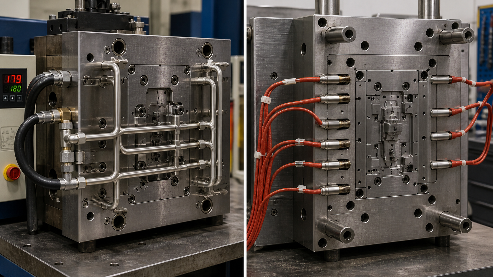
When I first started working with PEEK, I saw many shops use their standard oil heaters. It's a system they are comfortable with. Oil circulates through channels drilled in the mold, creating a "jacket" of heat. This method is fantastic for maintaining a stable, bulk temperature. For a relatively simple, blocky part, it can work perfectly. The moving fluid is very efficient at distributing energy evenly throughout the mold halves. However, oil has its limits. The maximum temperature is often capped by the fluid's degradation point, and it struggles to deliver focused heat to problem areas.
Cartridge heaters are a completely different approach. They are electric resistance heaters that you insert into holes drilled directly into the mold, close to the cavity. This is like putting a small, powerful furnace right where you need it. This method gives you incredible control over specific zones. If you have a thin core pin that's always running cold, you can place a small cartridge heater nearby to boost its temperature without overheating the rest of the mold. The downside is that you need more complex controls and careful placement to avoid creating hot spots.
Finding Cold Regions Before Resin Trials?
Running molding trials is expensive and time-consuming. Discovering a cold-spot issue only after you've injected expensive PEEK resin means wasted material, time, and effort.
We use thermal imaging cameras and multi-point thermocouple probes on the actual mold surface before introducing any resin. This thermal mapping process creates a clear picture of temperature distribution, revealing any cold regions that would compromise PEEK part quality, allowing for adjustments beforehand.
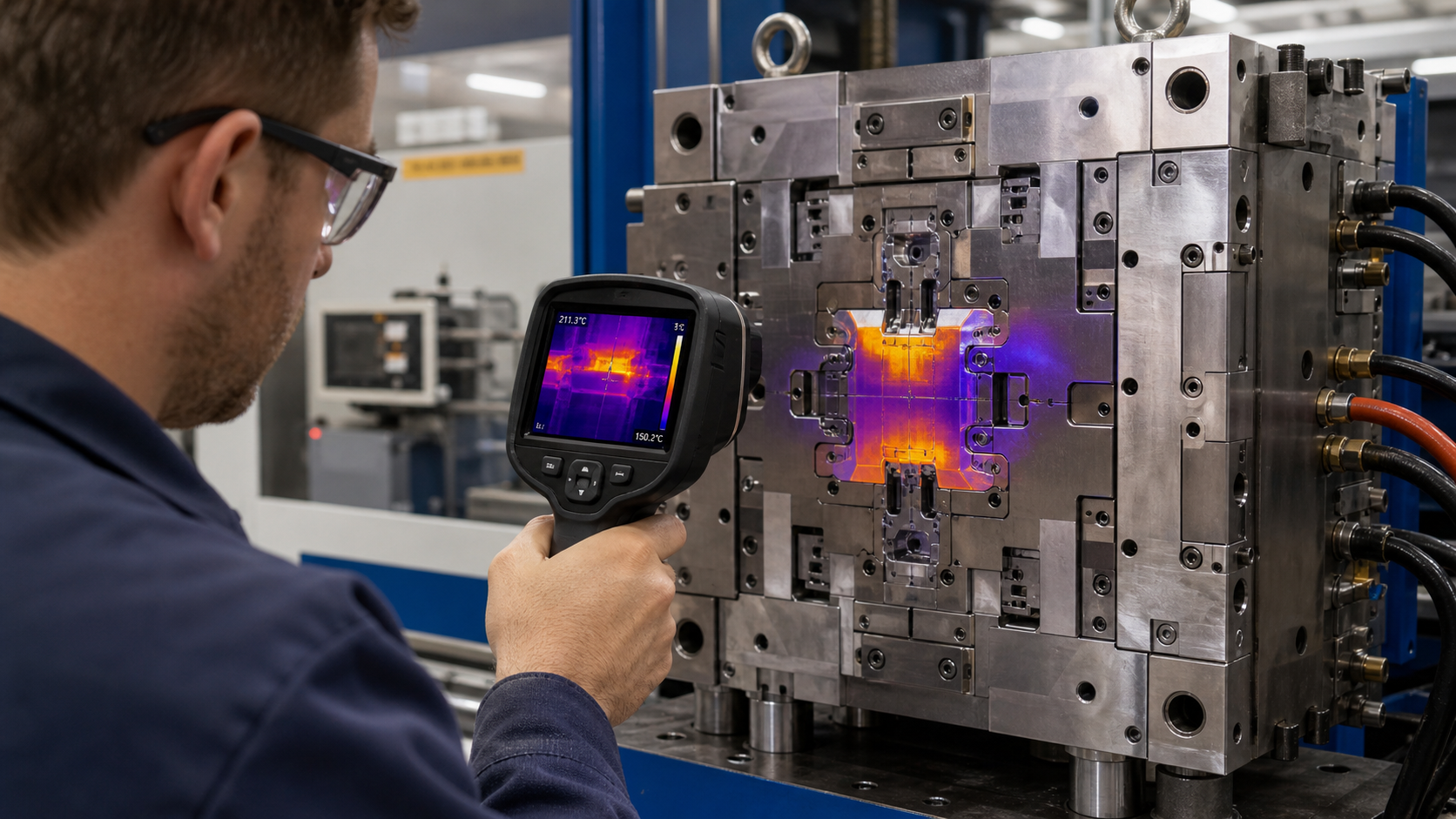
There is no substitute for real-world measurement. Simulations are helpful for initial design, but the way a mold behaves in the press can be different. Before we even think about loading PEEK granules, we heat the mold up to its target operating temperature and let it stabilize. Then, we get to work with our measurement tools. My preferred method is a high-resolution thermal imaging camera. It gives us an instant visual map of the entire mold surface. Cold spots show up clearly as darker areas, often around the edges, near water lines, or on complex inserts.
If we don't have a thermal camera, we use contact thermocouples. We identify critical areas on the cavity—thin walls, thick sections, corners, and core pins—and take multiple readings. We're looking for uniformity. For PEEK, a temperature variance of more than 5-10°C across the cavity can be enough to cause problems with crystallinity and warpage. Finding a 20°C cold spot at this stage is a huge win. It means we can solve the problem now by adding insulation, adjusting a cartridge heater, or even modifying the tool, rather than discovering it later through a pile of bad parts.
Selecting Heating Hardware Around Measured Uniformity?
You've identified temperature inconsistencies in your mold. Now you have to choose the right hardware to fix it, but a poor selection could make the problem worse or be a waste of money.
Once we have a thermal map showing where the mold is cold, we select hardware to deliver heat precisely to those areas. This could mean adding specific wattage cartridge heaters, implementing zonal PID controllers for better response, or strategically insulating parts of the mold to retain heat.
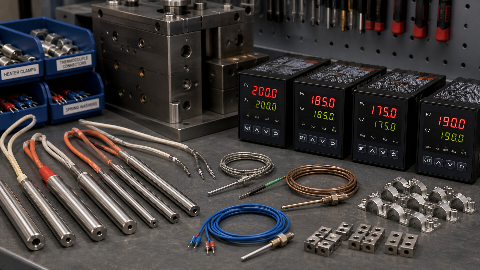
This is where the decision becomes evidence-based. If our thermal map shows the entire mold is running 15°C too cold but is relatively uniform, a more powerful oil heater might be the simplest solution. However, this is rarely the case with complex PEEK parts. More often, we find specific problem areas. For example, if a slide or lifter is consistently running cold, we would specify a high-watt-density cartridge heater to be installed as close to that feature as possible. We also look at the control system. A simple on/off controller isn't good enough for PEEK. We need a PID (Proportional-Integral-Derivative) controller for each heating zone. This type of controller anticipates temperature changes and makes smooth adjustments, preventing the overheating and under-heating cycles that can ruin PEEK's morphology. The selection isn't just about adding heat; it's about adding smart, controlled heat exactly where the data tells us it's needed. We retain the original polymer grade information and application limits; we never present this analysis as our own standalone test evidence, but as a process methodology.
Conclusion
Ultimately, we choose a heating system based on thermal mapping and part complexity. This evidence-based approach ensures the tool temperature is right for PEEK, avoiding guesswork and improving part quality.